Press power button after power outage with SwitchBot and ESP32

Being a cheapskate, I built my own Network Attached Storage (NAS) solution using a Raspberry Pi and a 5-bay USB3-attached RAID disk enclosure. This works great, and lets me run other processes on the Pi, including my Emby media server.

The one problem is that, when there is a power outage and power is restored, although the Pi boots up, you have to manually press the power button on the back of the disk enclosure. It’s an unfortunate design flaw, but I guess you get what you pay for 🙂 In my neighborhood, between the old infrastructure, numerous trees getting up into power lines, and Texas heat and wind storms, this happens somewhat frequently.

For a while, I’ve been thinking it would be nice to have a device that basically does one power-button-push upon power-up. I’ve googled around and haven’t found exactly the right thing, but I discovered something close.

SwitchBot makes the “SwitchBot Bot” (here on Amazon), which is ideally suited for pressing the button, but it falls short in a couple of ways:

  1. It’s more geared towards home-automation tasks – turning switches on and off on-demand, using a phone app to control it, setting up time-based actions…that kind of thing. There is no “press a button once after power is restored” function.
  2. It doesn’t connect to your AC power (which is nice), but to ensure battery life, it uses Bluetooth Low Energy (BLE) connectivity. So you kind of have to use your phone, although you can buy a “Switchbot Hub” for another 40 bucks.

So, being a long-time enthusiast of all things ESP (ESP8266, ESP32 microcontroller SOCs), my mind immediately went to the idea of looking for some code out there that might integrate the ESP32 with the Bot. The ESP32 includes on-board Bluetooth in addition to CPU, memory and WiFi.

I found two projects that I kind of borrowed from to create a working solution:

I started with the code here: https://github.com/mmglodekk/switchbot-esp32/blob/main/switchbot-esp32.ino but it did not work – commands sent never effected any action on the Switchbot. I ended up borrowing heavily from https://github.com/devWaves/SwitchBot-MQTT-BLE-ESP32, which has more robust scanning and command code, but since it is intended as an MQTT-to-Switchbot bridge, it had tons of code I didn’t need. 

My resulting code is here: https://github.com/acoulson2000/switchbot-esp32-power-on

I flashed an ESP32 MiniKit, connected it to a USB AC adapter and plugged it in right next to my drive bay. Now, whenever power goes out, when it comes back, after a few seconds, Switchbot turns my drives back on – this is soon enough for it to be registered by the Pi as it boots. I now have a more resilient home-grown NAS solution!

Posted in arduino, ESP8266, Technical | Leave a comment

ESP8266 SDK reboot loops with cause:2, boot mode:(3,6)

Recently I’ve been building and flashing some projects to the ESP8266 directly using the Espressif SDK for development (not Arduino).

After changing the flash mode, I was still in a reboot loop, but was seeing “rf_cal[0] !=0x05,is 0xFF” just before reboot. This is a known issue that is resolved by reflashing the “init data” (esp_init_data_default.bin) as described here: https://nodemcu.readthedocs.io/en/dev/flash/ (scroll to “SDK Init Data”).

The first thing to try is erase the flash before flashing your code:

esptool.py --port <serial-port-of-ESP8266> erase_flash

If that doesn’t work, flashing the “init” data will likely fix the problem:

esptool.py --port <serial-port-of-ESP8266> write_flash -fm <flash-mode> <flash_addr> esp_init_data_default.bin

Where <flash_mode> would be something like “dout”, “dio” or “qio” (use “dout” for ESP8285, “dio” or “qio” for ESP-12)

and <flash_addr> is determined based on flash size and this table:

  • 0x7c000 for 512 kB, modules like most ESP-01, -03, -07 etc.
  • 0xfc000 for 1 MB, modules like ESP8285, PSF-A85, some ESP-01, -03 etc.
  • 0x1fc000 for 2 MB
  • 0x3fc000 for 4 MB, modules like ESP-12E, NodeMCU devkit 1.0, WeMos D1 mini
  • 0x7fc000 for 8 MB
  • 0xffc000 for 16 MB, modules like WeMos D1 mini pro


Posted in ESP8266, Technical | Leave a comment

Trials and tribulations building and flashing ColorChord from scratch

In my efforts to create yet another improved version of my sound-response Light Suit, I elected to move to Charles Lohr’s excellent ColorChord project for sound analysis and LED driving. I wanted to add some functionality, though; mainly the ability to broadcast LED values as rapid UDP packets and some custom “modes” that didn’t involve sound (cycling rainbow, twinkle, all-on, etc). This meant tackling a task a bit more daunting than tweaking Arduino sketches – modifying and building the whole project, which is pure C code, not namby-pamby Arduino or LUA.

To document what I learned getting past some challenges for my own, increasingly poor, recollection, and for anyone else who wants to tackle this, I am writing this doc.

Since the directions are unix-oriented, I got a VirtualBox Ubuntu image to perform the build in. I used a version 16 build, but I don’t think the build is particularly sensitive to the version. I DID need to expand the root FS to 15GB and I allocated 2MB of RAM.

Create a work directory and change to it:

mkdir esp
cd esp

Clone the ColorChord repo, including the esp82xx subrepo:

git clone --recursive https://github.com/cnlohr/colorchord.git

Note: between October 2018 and now (Feb 2019), a bunch of changes to the esp82xx repo where merged in and seem to have resulted in this issue where setting the esp8266 to AP mode cause a crash loop. Hopefully the contributors will get that sorted out, but if you need AP mode now, you’ll have to figure out which versions of the main ColorChord repo and the esp82xx subrepo to pull in order to compile successfully and have AP mode working. 

Following cnlohr’s directions at https://github.com/cnlohr/esp82xx:

Create a shell script using the contents of https://gist.github.com/con-f-use/d086ca941c2c80fbde6d8996b8a50761 This is a script that will download and install the Espressif SDK and all the toolchain components and dependencies, then builds it.

NOTE: I had to first run the script as root (sudo su -) since it installs additional Debian packages. I did this from a directory under root’s home dir, since it goes on to download a bunch of files which are later built, but the actual build fails if run as root. So I run it in the directory under root, it fails with “[ERROR] You must NOT be root to run crosstool-NG”. I then deleted that temp directory and exited root back to my own user. Then I ran the script again. Since all the dependent OS modules are not installed, it gets past those steps and goes on to download the SDK files (again), and run the build.

ALSO, the script installs version 1.5.2 of the Espressif SDK. This version tends to not provide enough available “iram” to build colorchord. I got error messages like “image.elf section `.text’ will not fit in region`iram1_0_seg'”. This is a known issue with SDK’s after 1.5.1. To build using 1.5.1, after getting the toolchain built using the above, next follow this process as described here:

Download the ESP8266 nonos sdk v1.5.1 from espressif & delete the sdk provided because the provided sdk is v2.0 and above:

rm sdk
wget --content-disposition "http://bbs.espressif.com/download/file.php?id=1046"
unzip ESP8266_NONOS_SDK_V1.5.1_16_01_08.zip

Finally, enter esp-open-sdk and link the sdk v1.5.x back.

cd esp-open-sdk/
ln -sf ./esp_iot_sdk_v1.5.1 sdk

I then modified the SDK_DEFAULT and SDK paths in   <colorchord_install_dir>/esp8266/user.cfg to point explicitly to the toolchain and SDK locations.

At this point, it should be ready for compiling ColorChord and flashing to your ESP.

“Attach” the USB serial port via the Virtualbox. To do this, you have to enable the USB driver and 2.0 support in the guest settings and install the driver in the guest. Then, you have to attach it once the guest is started via the little USB icon in the status bar at the bottom of the guest window. I also have to change permissions on the serial device every time I mount it since I am executing all the build stuff as myself, not as root.

sudo chmod 666 /dev/ttyUSB0

After that, you build and burn – but NOTE – I also needed the to run the “initdefault” make stage. Without it, I had an esp that just crashed on startup:

make all
make initdefault
make burn
make burnweb

After all that, you should have an esp that starts up, logs stuff to serial, and enters AP mode, at which point you should be able to connect to it via wifi, browse to 192.168.4.1 and see the cool sh!t!

Once you’re connected, you can configure it to connect to an Access Point instead of acting as its own (which bogs down the framerate). After setting the ssid and password, reboot. To fin it on the network, use dns-sd commond line tool. Downlaod form here: https://developer.apple.com/opensource/ under Command Line Tools. It’s in the Bonjour SDK for Windows.

Use this to enumerate the device:

dns-sd -B _colorchord._tcp

Then ping the Instance Name if you want the IP address.

Posted in ESP8266, Technical | Leave a comment

Light Suit V3

Coming sooon!

Posted in Uncategorized | Leave a comment

Multi-Zone Audio Streaming on a Budget

Note – all the parts I refer to in this project are listed at the bottom of this post…

Not long ago, we purchased a rental property that came with “architectural” (or in-wall) speakers in several rooms and outside on the deck. I spent some time ruminating on what to buy to hook them all up to so that we, and guests, can listen to music in the different zones and – in the case of the speakers mounted on either side of the TV in the living room – pipe the cable tuner audio through those speakers.

You can get multizone tuners, but I have several issues with them:

  • They’re pretty pricey
  • They tend to only support a couple of independent sources –  you can’t, for example, have different audio sources playing in three zones…unless you get REALLY pricey
  • They’re complicated! I, myself, have trouble figuring out how to get those things to play a different audio source to the second channel, especially using the remote. My wife would never be able to do it, and I think it would frustrate guests.
  • Nowadays, people tend to have a bunch of music on their phones…or maybe subscribe to Spotify or whatever…that they want to play in the room they’re in (or outside)

So I was thinking, what would be nice is a system that let’s you stream music from your phone to any one of the various zones (or, in the case of the living room, choose Line-In to get the cable audio). Does such a system exist? Sort of.

After some googling around and looking at various devices currently available, I settled on the Dayton Audio WF40A “Multi-Room” WiFi 2x20W Amplifier. This is a little device that hooks up directly to your speaker wires and can connect to your network via either WiFi or Ethernet. It also has a line-in connector.  It can also operate in “Stand-alone” mode, but you’d have to connect phone to it’s access point instead of the general house WiFi. Using a phone app, you can stream music directly off your phone or use one of the supported streaming service, including iHeartRadio, Spotify, and a couple others. Actually, it’s a DLNA device, so any app that can play to a DLNA “sink” device should be able to stream to it (including the iPhone music player). You can also select Line-In as the source. It costs around $100.

So, my trial with that device went pretty well and I was considering adding 3 or 4 more zones…maybe over time rather than plunking down several hundred bucks at once. But, being a gadgeteer, I thought I’d look into whether weren’t some inexpensive components available that I could put together to do the same thing for a lot less. Naturally, the answer is YES!

There are a whole plethora of devices for around $30 that give you the streaming ability, including the WFA02, also from Dayton Audio (which seems like a somewhat more “reputable” company), although they don’t include integrated amplifiers. I actually went with an even cheaper version that was available under a dozen different names (but all say AudioCast on the case) on aliexpress.com for about $24 a piece. Heck, there’s this one for $17 (so cheap it scared me off). There area ton of cheap little stereo amplifier boards that claim to hand up to 50W per channel available online for about $5 though! They take line-in and drive a pair of 8ohm speakers. You have to provide power to them, They tend to take 5 to 24V DC as input. A little research revealed they’re all using one of a couple different audio amp chips, so it’s mainly a choice of form factor, what kind of jacks are integrated (if any), whether there is a volume knob, etc.

“AudioCast”

Audio Amp Board


So… I wound up buying three of the little “AudioCast” WiFi gadgets for about $24 each, three audio amp boards, and a hefty 10Amp, 12V power supply intended for driving LED light strips – I think it’s pretty much just a switching power supply very similar to the ones that come with laptops. I chose an audio amp board that has an audio-in jack, making hookup easy, and a volume know (so I can potentially limit how loud guests drive the speakers). All-in, it cost me $104.

I also bought some plexiglass and some nylon stand-offs so I could put the whole thing together in a somewhat neet and “protected” package – that was a few bucks more. For convenience, I also bought a power strip that includes 4 USB ports, so I can power the whole contraption from the one power strip.

Here are a couple pictures of the assembly (not yet wired to speakers):


The audio boards, though quite small, seem to pack a pretty good wallop. I don’t have a good, decent poser speaker at home – I could only hook it up to a PC I had – but I turned the volume up till it was pretty loud. I didn’t want to blow the speaker, so I was afraid to turn it up all the way. Even at “pretty loud”, it wasn’t turned nearly all the way up, and the heatsink didn’t even get warm. Despite being small and inexpensive, I’m optimistic that these will drive the in-wall speakers pretty well. Hopefully, the 10Amp power supply is sufficient to drive all three zones at once, but I have a feeling if all three are cranked all the way up, it may be insufficient…we shall see.

A couple interesting things about these inexpensive WiFi streaming units…  There are probably a half dozen different varieties of them, and the “AudioCast” shows up under all kinds of different brand names. Different varieties point you to different phone apps – the two Dayton Audio devices say to use “Hi-Fly”, other products direct you to “AudioCast”, “MUZO Player”, “ESON”..and probably others. The funny thing is…they’re all essentially the exact same app, except with minor branding variations and slightly different streaming service choices (some of which are quite bizarre Chinese things):

Dayton Audio Hi-Fly

“MUZO”


So, these function just the same, use essentially the same app…who wants to bet they have the same guts? And low-and-behold! On one Aliexpress AudioCast-type device, they show the guts – its essentially just a carrier board with a few components and a Linkplay A31 plugged into it. Parts-Express.com is the authorized distribution partner for these Linkplay things – they sell just he A31, as well as an eval board and, yes, a combo with a little carrier board that includes an ethernet port and line in/out connectors. So yeah, probably most of these devices are incorporating the same little board and the manufactures license the same app (which the get to brand a bit). Sadly, these little bare-bones kits cost more than buying a product from China (or even from Dayton Audio) that has one inside it!

I’ll post an update on how the installed system behaves soon.

Parts I used:

Dayton Audio WF40A Multi-Room Wi-Fi 2x20W Amplifier with IR Remote

Dayton Audio WFA02 Multi-Room Wi-Fi Audio Adapter  (no amp)

“AudioCast Wireless Multi-Room Music Streamer”

12V, 10A Power Supply

Nylon standoffs

Power Strip with USB ports


Interesting LinkPlay stuff:

LinkPlay main page on Parts-Express

LinkPlay A31 on it’s own

LinkPlay A31 eval board

LinkPlay A31 Integration Board w/IR Remote


Posted in Uncategorized | 3 Comments

Dahua DH-SD22204T Security Camera

I recently decided to install an outdoor PTZ security camera at our beach house to keep an eye on the premises, not to mention the threatening tide line during storms. After installing a “Sumpple WiFi Wireless PTZ” outdoors, it lasted about two weeks before becoming completely non-responsive. Total Crap.

For my second try, I ordered a Dahua SD22204T-GN, which is actually about $15 cheaper, supports PoE, but doesn’t have WiFi. This is fine with me (actually preferable) in this case – it turned out the WiFi signal was so weak where I want to mount the camera, I had to run 10BaseT to it anyway. PoE gives me a more convenient way to run power to it and replace the power supply, if it goes out. This time I paid an extra $5 for the insurance, so if it dies, it’s going straight back for a full refund and I’ll move on to another one 🙂

So far, this seems like a very good camera for the price. I have not installed it outdoors yet, but checking it out on my desk, it seems solid. The image quality is quite good, even at night. Although the camera has no IR LED’s, the light sensitivity is very good and I get a good image with only a small amount of ambient lighting. The web interface is robust, although live video doesn’t display natively in Google Chrome – you will have to install the “NACL” plugin. Also, although the camera does support built-in motion detection, it doesn’t have a nice feature that the Sumpple had to run a remote (ssh) command, which let me send a text via Twilio from my home server. It does support typical options to record to SD card, FTP a captured recording, or email. The email option works for me, since I can email my phone’s SMS address, but is a little annoying because it sends three  event emails; “Start”, “Recording” and “End”. I wound up setting up a “go-between” email account with a filter to only forward the “Recording” event to my phone. This onb of the three also includes a thumbnail (although occasionally the thumbnail is not present for some reason).

To install an SD card or mount the camera to a surface, you will need a T10 torx bit, as the enclosure is fastened with “tamper-proof” torx screws and the surface mount holes and SD slot are internal – not necessarily a bad thing.

Some useful information for anyone trying to use the camera with ContaCam:
I wanted to use the camera with ContaCam and it took some trial and error to get a connection to work. I finally used the following connection string with my user credentials in the “Camera login” section:
rtsp://<your_IP_address>/cam/realmonitor?channel=1&subtype=0&unicast=true
Use subtype 0 for the main stream or 1 for the secondary stream.

A more “generic” url that works with VLC is:
rtsp://<username>:<password>@<your_IP_address>/cam/realmonitor?channel=1&subtype=0&unicast=true

Posted in Uncategorized | Leave a comment

ESP8266 with ILI9341/XPT2046 TFT Display w/ touch

These 2.8″ 240×320 pixel color TFT displays for $8-10  can be found on ALiExpress. There’s also an equivalent-looking one offered by AdaFruit for $30 if you want one fast – the pins are quite differently label, but I’m willing to bet it’s virtually equivalent. I just LOVE AliExpress – stuff is SO CHEAP! But, as is usually the case, the Adafruit one is well-documented..the Chinese version, not so much. There are a smattering of posts and github libraries out there, but none document very clearly exactly how to hook one of these up, so I will describe here how I got one working.

I first spent a bunch of time trying to get one of the libraries that was coming up a lot for the XPT2046 touch functionality to work. That XPT2046 library seems to be the “standard” out there, but there’s no clear documentation of the hookup and it uses a somewhat cumbersome library for the TFT display.

The key that finally got me going was this blog post – it was one of the most useful, since it has a good hookup diagram, which I’ll include here, in case the post goes away. That post also refers to the XPT2046 library for touch input, but uses the AdaFruit TFT Driver and even includes a zip file containing the AdaFruit driver and examples comprised of versions of the XPTCalibrate and XPTPaint sketches modified to use the AdaFruit display library. With those samples and the help of the hookup diagram, I was able to get things working. The diagram is a big help, since the pin labels on the cheap Chinese board don’t really match what is referred to in sample sketches. Also, it isn’t completely intuitive that you need to connect the SPI pins (SCK, CS, MOSI & MISO) to the standard pins for those signals on the ESP8266.

Once I got the pin hookup figured out, I was also able to get the sketches included with the XPT2046 library working – they use a display driver (which you also have to install) authored by the same developer, but I wound up using the AdaFruit driver for the ILI9341 TFT. It is based on AdaFruit_GFX and offers a lot more functionality, including a convenient button-drawing-press-detection framework.

Overall, this is another one of those components that just blows me away for being so cheap (especially when you buy it from China), but giving you such impressive functionality. In my next post, I’ll outline how I incorporate this into a wrist-controller form my LightSuit Version 3.

Posted in ESP8266, Technical | Leave a comment

ESP-01 V3 Doesn’t Reset or Run

I recently ordered a set of 10 new ESP-01’s from China.  After the usual few weeks, they arrived. I pulled one out, plugged it into the socket on my little interface board – which has buttons for RST and GPIO0, a 3.3V regulator, and pins to hook my USB-to-TTL cable to. That little board makes it really easy to program these minimal-feature ESP8266 boards.

So, I go through my process of setting the board options in the Arduino IDE, clicking “Program”, and then holding down the GPIO0 button, while momentarily pressing RST. I immediately noticed that I didn’t see the usual short flash of the LED (which is connect to the TX pin on ESP-01 boards). It then failed to write to flash. After some experimenting, I could get it to write to flash by holding GPIO0 down while plugging the USB cable in. However, my sketch didn’t seem to execute. I hit RST again and nothing happened. Reset was definitely not doing anything, and no matter what I did, I couldn’t get my sketch to run (I knew it worked, because I could flash it to an older ESP-01 and it ran fine).

So finally, after googling abit, I discovered that people are sometimes now receiving “V3” versions of the ESP-01. This seems to vary a bit between different vendors – some still ship V2’s, some send V3’s. And the difference on the V3 is that there is now a 6K resistor inline with the pin on the ESP-01 and the RST pin on the actual chip. This seems to prevent RST from working and prevents the chip from entering run mode on power-up. The post I found included the following picture illustrating where the resistor is. With some relatively fine soldering skills, you can remove the resistor and solder a fine jumper wire in place, which solves the problem. DON’T FORGET that you also have to pull CH_PD HIGH for the chip to enter run mode – I usually solder another jumper directly onto the ESP-01 to do this, except in cases where I what to have control over the chip entering low-power mode.

With this set of chips, I also had better luck using the “Generic ESP8285 module” profile.

This is also documented on the ESP-10 wiki here: https://www.letscontrolit.com/wiki/index.php/ESP-01#ESP-01_v3


Posted in ESP8266, Technical | Leave a comment

Wine Fridge Temperature Controller – V2

In a previous post, I described how I replaced the highly-proprietary power supply on min wine refrigerator with an off-the-shelf supply and a Monster Moto shield to drive the fans and termoelectric peltier heat sinks based on the PWM (pulse-width modulated) signal from the controller head unit.

Recently,  I noticed the actually temperature was no longer tracking to the set temperature. Then, a couple months after that the supply completely died again. I guess the temp being off was a symptom of it dying. In any case, it was time to look at replacing it again. Last time, I was never completely happy with the klugey way I massaged the PWM signal to drive the cooling components – it never really got to where the PWM duty cycle was ON a high percentage, so it didn’t cool fast or to low temperatures. I knew what I really needed to do was put a smarter controller on the Moto shield (like a real Arduino) so that I would have full software control over the PWM driving signal. The Monstor Moto shield is intended for an Arduino in any case.

This time around, I decided to do that. This would mean effectively replacing the “head unit” too, since it had a small embedded processor that was responsible for taking input from the temp up/down buttons, the temp sensor (an NTC thermistor, I believe), driving the LED temperature display, and producing the PWM signal that controlled the original power supply output power. Rather than try to cut up the head-unit circuit board, re-route the buttons to the Arduino, and figure out how to drive the 2 8-segment LED temp display, which would require additional circuitry or some kind of display driver board, I decided to use an ESP8266 board with an OLED display in the front-end. This had the added advantages of giving me full software control over cooler operation and making it  very easy to WiFi-enable my fridge 🙂

I bought a different, higher amperage, power supply to cannibalize – I figure that will help keep it from burning out. It also has an integrated fan, which I’ll drive off the same PWM-moderated output voltage.

12V 15A AC to DC Power Supply

12V 15A AC to DC Power Supply

This is a link to what I bought – Home Usage AC-DC 12V 15A 180W Adapter Converter with Car Cigarette Lighter Socket. In case the link dies, it looks like this:

Turns out the fan was quite loud, so I also bought an “ultra quite” 12V 50mmx50mm fan off of eBay.

I found an ESP8266 board which had an on-board 32×90 pixel OLED display: The Heltec “WiFi Kit 8”

I added an Arduino, which actually drives the Moto Shield now. It also reads the temperature sensor. Based on the temperature reading, it adjusts the PWM duty cycle to be more or less aggressive about cooling, based on the difference between the “target” temperature and the measured “current” temperature.

Determining the temperature wound up being more complicated than I hoped. At first, I tried a little Arduino routine I found on the Arduino Playground for deriving temperature from an Thermistor connected to an Analog Input pin, but it was giving me values that were way out of whack…not sure why. I probably could have integrated a digital temp sensor, like the DHT11 or TMP102’s that I’ve used before, but I wanted to use the existing wiring that goes between the internal “head unit”, penetrates the enclosure, and ends where the power control circuitry is, which limits how many conductors I can use.

The internal temp sensor already had the wiring in place, and was nicely positioned in the air-stream of one of the internal fans. I wound up putting a TMP102-based ESP8266-connected sensor I use to monitor my bedroom temperature (for home automation purposes) inside the fridge, and wired the temp sensor to the Arduino A0 pin using the circuit from the Arduino Playground page. I then wrote a test sketch that drove the Moto shield and cooling hardware at constant duty cycles and logged the analog reading of the sensor connected to the serial port. I was then able to create a graph in Excel that correlated actual temperature to Analog reading:Capture

As you can see, this produced a very predictable and linear trend line. From that I was able to write a very simple routine derived from the the starting point of a reading on 830 (60°) and the slope of the line – see my Thermistor() function in WineCoolerDriver.ino. I also average multiple analog readings together before calling the function function, since the analog inputs can be a bit “noisy”. I also average ten temperature readings over time and base the PWM duty cycle on this moving average to reduce “jitter” in the “current” temperature and the duty cycle driving the cooling hardware.

I use the ESP8266 board to display the current temp and target “set_point” temperature. It also provides a WiFi interface for setting the target temp and ready the current temp values. I connected the ESP8266 to the Arduino over two of the available conductors over a “serial2” port using the SoftwareSerial library (leaving the Serial port on both boards available for debugging and  diagnostics). The ESP8266 periodically sends a one-byte target temperature setting to the Arduino, and the Arduino periodically sends the current temp to the ESP8266 for update of the display.

Here’s a Fritzing diagram of the Arduino, Moto, ESP8266 and sensor. See the last post which shows connections to fan/peltier assemblies.Fritzing

I actually added a couple of buttons (not depicted) (GPIO13 & 14) on the ESP for direct temp control.

Here’s the Moto Shield and Arduino assembly: IMG_20180204_100325742

Note that I stuck some stick-on heat sinks on either side of the VNH2SP30 chips,a s they seemed to get pretty hot under full load. That necessitated adding some extra risers between the shield and Arduino for clearance.

Here’s the Assembled “front-end”: IMG_20180209_080934852.jpg

I expanded the little window to accommodate the wider OLED and just cut a hole for the LED push-on/push-off button.

IMG_20180209_081000791.jpg

I also glued a couple of push-buttons in place behind the temperature up/down blisters (they are embedded in the white glue) and I used some Polymorph thermoplastic to form a sort of “bracket” that holds the board in place without being permanently attached. I highly recommend checking out thermoplastic – it is super versatile. You just heat it in boiling (well, not even boiling…) water. It softens at 150 degrees, at which point it’s like putty, then it hardens to normal plastic hardness when it cools.

Here it is fully operational:IMG_20180211_121133237


Posted in arduino, ESP8266, Technical | Leave a comment

Wine Cooler Power Supply

I’m just going to blog about this one briefly, in case their are any other enterprising Wine Cooler owners out there who find that, two years into owning their cheapo wine cooler, the power supply craps out. I didn’t take pics all the way through, so it won’t be much of a step-by-step build log.

A couple years ago I bought a “AZ-EA45EC-75” on Amazon. If you read reviews for these wine coolers, you WILL notice that there are more complaints about the cheaper ones breaking down after a year or two (often out of warranty). But I figured the price differential was worth it, especially if I got one  that is cooled via Peltier thermocouples, since I’d have a chance at repairing it if something went out.

Sure enough, a few months ago, the power supply went out. I can troubleshoot basic electronics, but troubleshooting a switching power supple (which this thing had) is a bit beyond me. I did try replacing some darlington transistors that showed a lot of heat discoloration on the circuit board, thinking they might have burned out (one was not very well secured to the large heat sink). No go. Maybe there was a cascade failure or something…i think maybe the winding on one of the very specialized transformers was also out. I even succeeded in tracking down the Chinese manufacturer of the power supply (the website was printed on it), and emailed them to see if I could just buy one unit. After a couple tries, I actually got a response (in bad english) that I think said I could send it to them and they would repair it for, like $80, and send it back..with me paying shipping both ways. No thanks.

In pulling the thing apart, I learned that the cooling system consists of the switching power supply, two thermocouples – each with an outside and an inside fan which look like typical PC power supply fans – some kind of internal temp sensor, and a little control board that includes the temp control buttons and current temp readout. Oh, and a little LED light array inside that you can turn on and off with a button on the control panel. They all connect to the power supply. The thermocouples and fans are just 12V powered, but clearly there is some logic somewhere to throttle how much power goes to them, since it would work harder when trying to cool down, but bee nearly silent when the internal temperature matched what you set the controller to.

The controller board had a 5 pin connector, and it was actually labeled: 12V, Gnd, LED, NTC, and PWM. I guessed (correctly) that LED controlled power to the light – I think it was just wired straight though on the power supply, since 5V regulated came out on that pin, and the LED array required 5V to light up. PWM was interesting – my guess (again, correctly) was that they Pulse Width Modulated the power to the two sets of thermocouples and fans. To verify this, I finally broke down (after 30+ years!) and bought  an inexpensive USB-based oscilloscope. I bought a Sain Smart DDS-120 for about 150 bucks and it was totally adequate for my needs…and now I finally have at least a cheap o-scope!

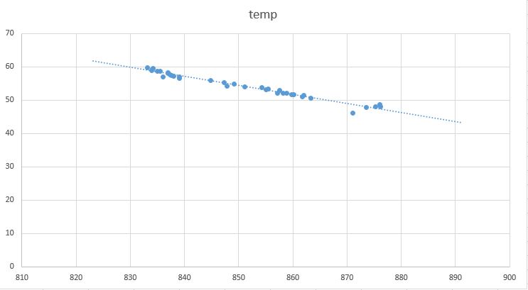
Anyway, using the o-scope, I verified that there was a 5V square wave coming out of the PWM in. Actually,  first I had to figure out what “NTC” was. Initially, providing 12V to the controller made the LED readout light up fine (and the LED button controlled whether 5V came out on that pin or not), but the readout would flash a few times, then show “E1”. I though on it a while and figured maybe it needed to sense a temperature to work. Turns out, it’s common to sense temperature with is an “NTC”  thermister 🙂 I wired a resistor in the 10K range across the NTC pin and Gnd and – sure enough – the readout would show 59°. When I turned the temp down below 59, the “off” period of the PWM square wave was longer – when I set the temp over 59, the “off” period got shorter. So, the “off” time of the PWM theoretically drives the power to the thermocouple clusters…kind of an inverse relationship..not a big deal, since I could easily invert that signal if necessary.

I started casting about for an easy way to drive a fair amount of power via the 5V logic signal from the PWM pin – from googling around, I estimated that driving a thermocouple and a couple of fans at full power could eat an amp or more. I prefer to find pre-assembled boards for more complicated circuits, since assembling a lot of discrete components can be pretty error-prone, plus I’m just not that great at linear circuit design. After looking around a while, I decided on the Monster Moto Shield. Intended to drive robot motors, this sucker can sink a lot of current. As the name implies, it’s intended to be used with an Arduino, but I just hard-wired the control pins to the appropriate logic level and tied the PWM pins to the PWM out from the fridge controller (after going through a couple of inverter components, described below).

I should say, in between all this – which took place over a week or two – I temporarily rigged up one thermocouple/fan set to just run continuously off a 12V laptop power supply I had lying around. This actually worked pretty well. Since I was just running one, it seemed to keep the cooler chilled, but not too cold. I even considered making it more permanent, and just buttoning it up and blowing off temp control, but that would have been to easy 🙂

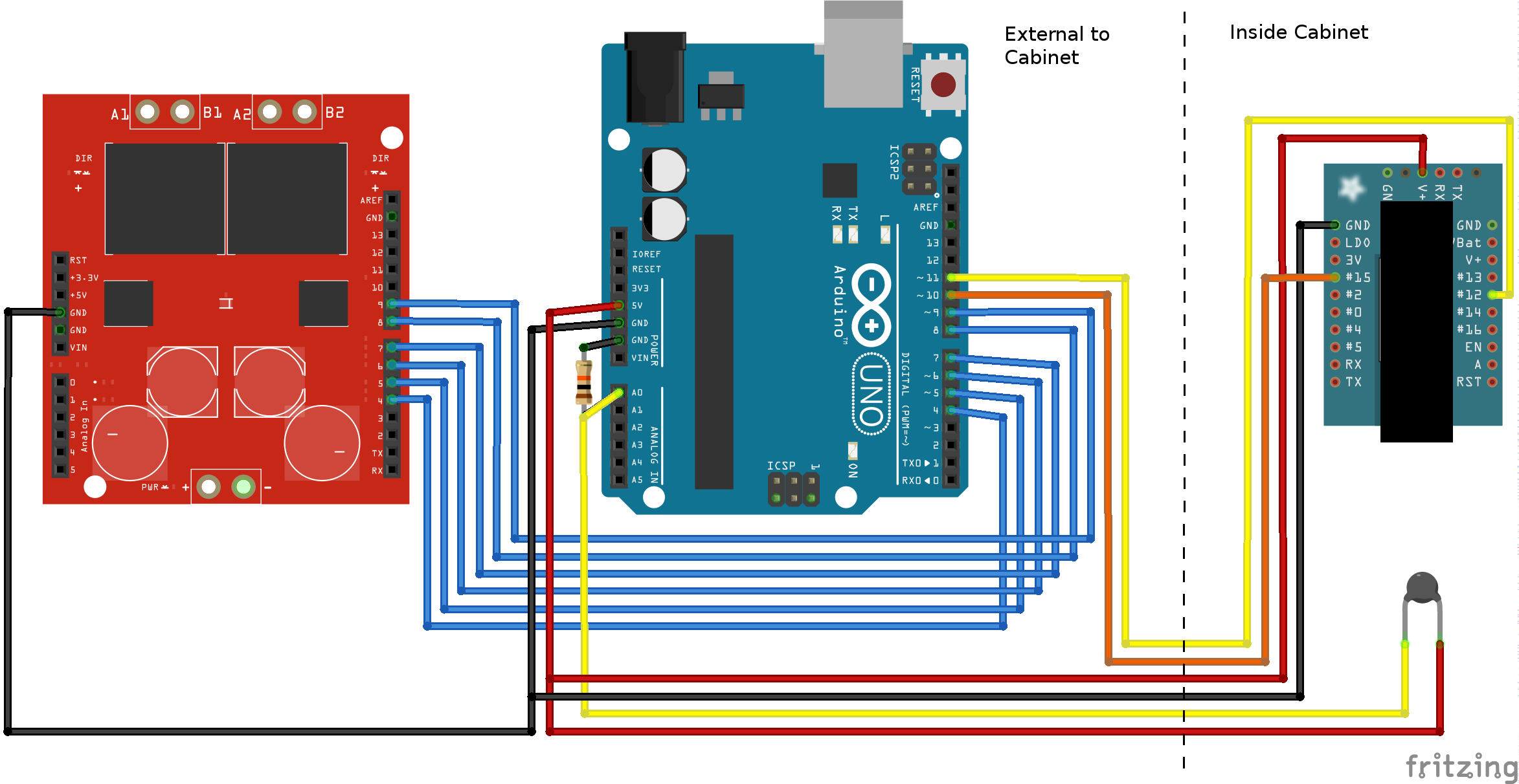
Here’s a rough Fritzing diagram of the whole rig.WineFridgeFritzing_bb

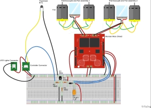
I used a simple NPN transistor, to invert the signal coming from the controller board, tying the PWM inputs of the two Monster Moto channels to the “high side” (collector) of the transistor. So, when the signal coming out of the controller is low, the driver side is high and visa versa.

Update (4/28/16): As I tried this rig out hooked up, I discovered that it had trouble getting the temp below about 58°. This seemed to be due to the fact the the PWM duty never really got above more than about 60%. I added a low-side resistor on the transistor emitter to bias the output higher, then a diode and a capacitor which effectively “store” some of the “on” energy, while the diode prevents leakage backwards. This smoothed out the output, but also biased it slightly higher, resulting in more time above the Moto shield’s PWM trigger level. I basically picked the values by just experimenting – in fact, I’m not even positive of the cap value – I just found one in my tray of caps that was in-between doing almost nothing and causing the PWM signal to basically be always-on. 

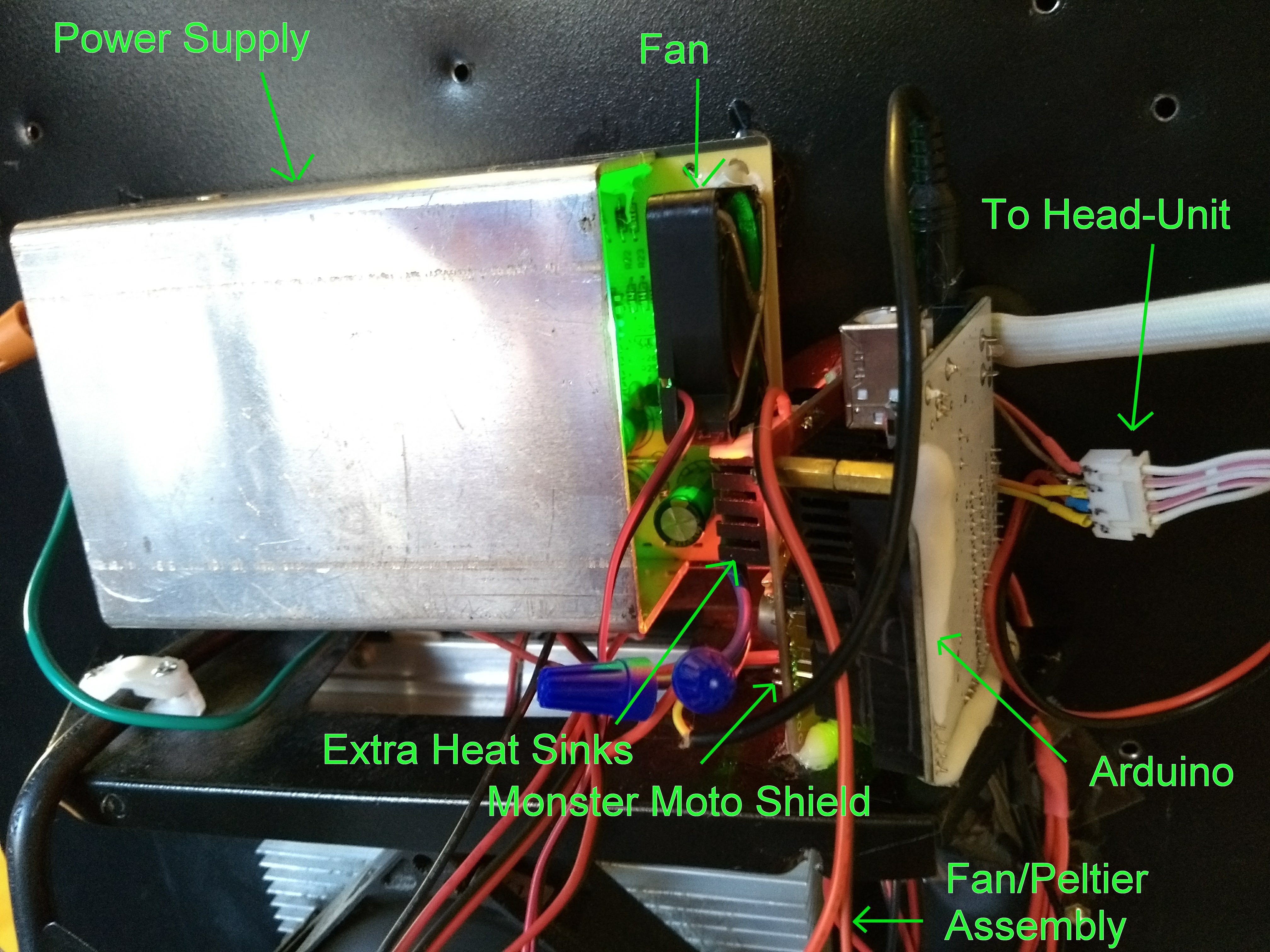
I bought a cheap 12V switching power supply capable of delivering multiple amps from China. Here’s a picture of the whole thing rigged together temporarily. It looks like a rats nest, but will look a lot better when I consolidate all this into just the power supply, Moto shield, and a little daughter board.ratsnest

The Moto shield gets pretty hot when it’s really cooling, so I stuck a couple of little heat sinks I had to the two VNH2SP30’s, and even they seemed inadequate, hence the extra aluminum foil 🙂 For a more permanent solution, I’ve order a half dozen 20mm x 20mm heat sinks from Amazon that should arrive in a couple of days.

Total cost for all this – about $50. That’s not included the O-Scope, but everone deserves an o-scope! And of course, time…I spent a lot of that reverse engineering and tinkering with getting the input levels right on the Moto pins. Definitely a cheap fix, PLUS now I have something that’s much more maintainable, since I basically put the whole power circuit together myself.

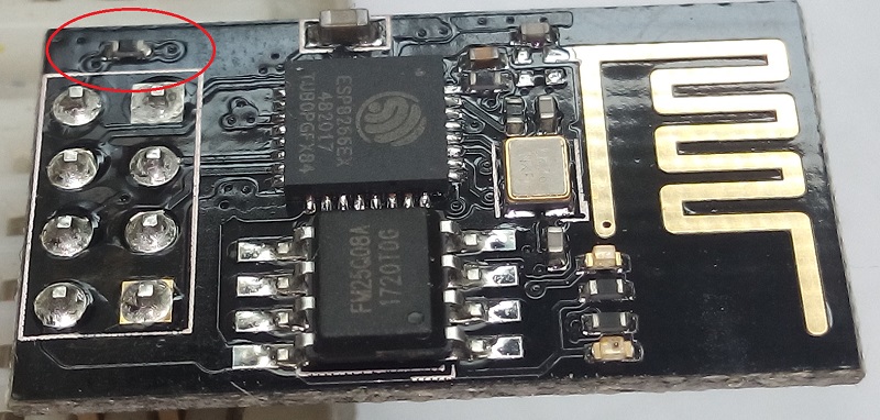
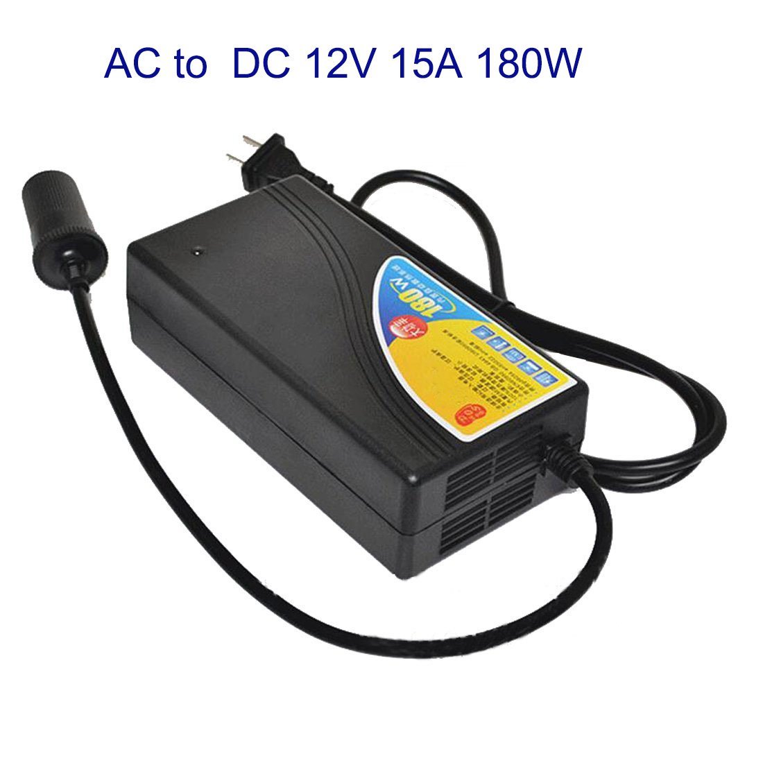
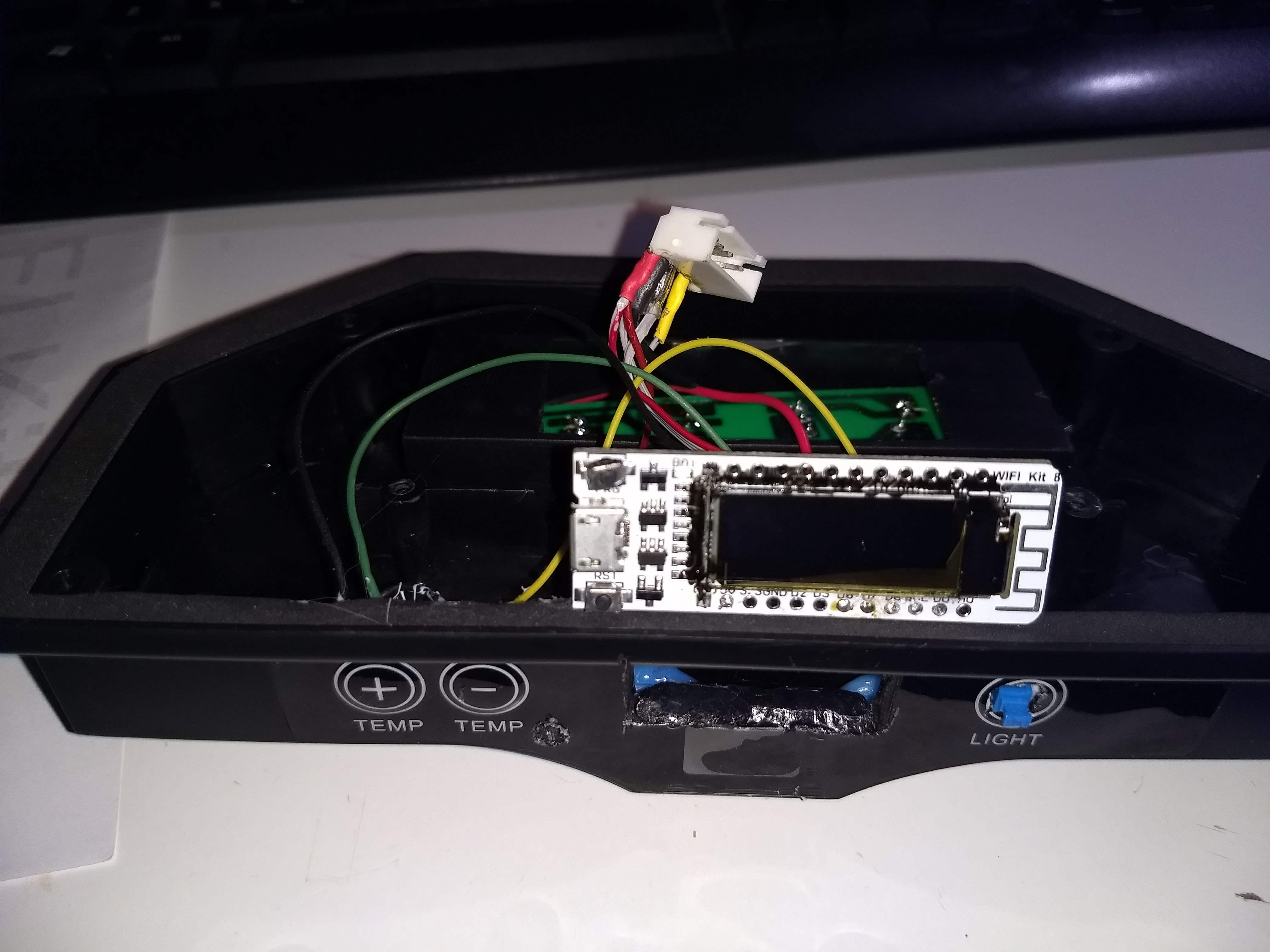
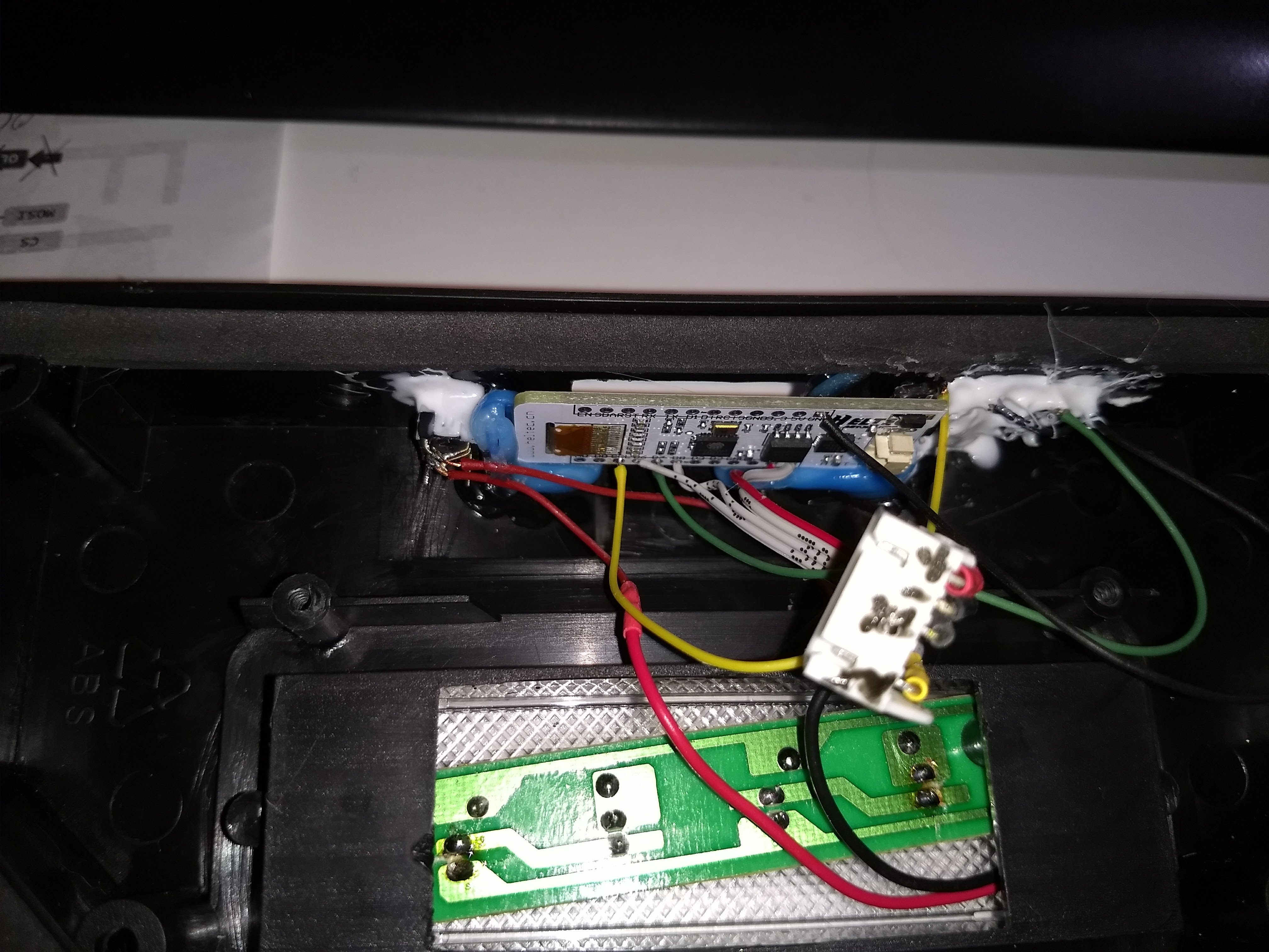
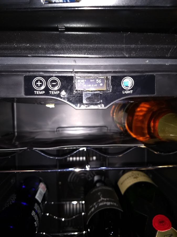
Update (1/25/2018): Well, my cheapo Chinese power supply burned out – these things really don’t last well! I think part of the problem may be poor ventilation around the supply. Anyway, I bought one of these: https://www.amazon.com/gp/product/B01ET14J8O for about $35. It has an integrated fan, which I hope will keep it cooler and help with lifespan. I intend to remove the case and just mount the guts to the wine cooler. The fan is actually kind of loud, so I may also order a quieter 50mm 12v fan. I also wasn’t very happy with the above circuit to drive the Moto shield from the PWM signal – it was never getting below about 57 degrees – I guess because the square wave didn’t have enough “on” time. So I’m just going to replace the control circuitry entirely with an Arduino. While I’m at it, I’m going to wire in an ESP8266 with an OLED screen to display the temp and let me monitor and set it via WiFi. It’s not lost on me that, at that point, aside from the thermocouple-and-fan assemblies, I’ll have practically built a wine cooler from scratch :-/  Actually…maybe there’s a business in custom wine-fridges… Anyway, I’ll do a post about it shortly.


Posted in Technical | 1 Comment